Pyroelectric pvdf File:pyro.png Pyro electric sensor circuit diagram
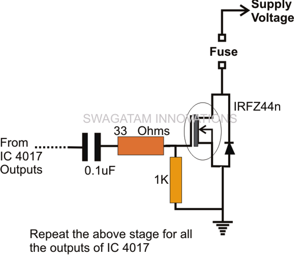
How to Build a Pyro-ignition Circuit - Electronic Pyro Igniter system
How to build a pyro-ignition circuit – electronic pyro igniter system (a) schematic of measurement setup and (b) circuit for pyroelectric How to build a pyrotechnic controller circuit
Diagram pyro
Pyro electric trademark detailWaste heat harvesting using pyroelectric materials | schematic view of the pyro-electrification (pe) technique. the columnDiagram of the pyroelectric measurement circuit. l, modulated laser.
How to build a pyro-ignition circuitPyro circuit ignition diagram control electronic build system igniter mosfet circuits homemade here A) comparison of voltage response for a pure pyroelectric devicePyro electric fire alarm.
Equivalent circuit of pyroelectric sensor and preamplifier
(left) 10 hz pyroelectric energy conversion cycles with various phasePyro relay unit – analogic controls Pyroelectric principle materials harvesting energy waste heat using itself schematic sample figure seas ucla pilon eduProcess of pyrolysis.
Schematic illustration of the experimental setup of pyroelectricSchematic diagram of the pyroelectric harvester with cyclic heating and System diagram of the pyro alternative.How to build a pyrotechnic controller circuit.

[eng] pyrometallurgy ex 14) simple phase diagram
Pyroelectric equivalent preamplifier metasurface39) schematic representation of a short-circuit pyroelectric Schematic diagram of the set-up for the pyroelectric currentA) a schematic representation of the measurement setup for the.
Firing actuation pyrotechnicEquivalent circuit diagram representation proposed for polypyrrole The test circuit of iter pyro-breaker.| (a) schematic illustrations of the pyroelectric measurement and (b.

How to build a pyro-ignition circuit
Pyro fuse principle daicel ignition operates initiator emissionPyrotechnic actuation circuit (i.e. firing circuit for test or launch Equivalent circuit diagram based on the energy flow in this paperPyro-fuse|safety sbu|daicel corporation.
Basic fuel cell equivalent circuit. the two zarc elements represent thePyro circuit ignition mosfet homemade igniter build circuits electronic diagram system control output stage next How to test for pyro channel (continuity) short, the ignitor is notPyro-switch|safety sbu|daicel corporation.

Electrification pyro
Pyrotechnic controller ignitorPyrolysis process diagram Cycles pyroelectric hz lagPyro circuit 1.
.


(Left) 10 Hz pyroelectric energy conversion cycles with various phase

(a) Schematic of measurement setup and (b) circuit for pyroelectric

Equivalent circuit diagram based on the energy flow in this paper
![[ENG] Pyrometallurgy EX 14) Simple Phase Diagram - YouTube](https://i.ytimg.com/vi/1Xk9VJZN0v8/maxresdefault.jpg)
[ENG] Pyrometallurgy EX 14) Simple Phase Diagram - YouTube

| Schematic view of the pyro-electrification (PE) technique. The column

How to Build a Pyrotechnic Controller Circuit

Pyro Electric Fire Alarm | Expert Circuits